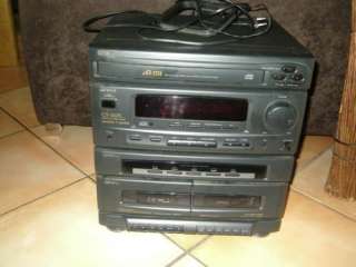
Aiwa Cx Nd77 User Manual

 admin

The Yorozuya is soon approached by Nobume Imai and two members of the Kiheitai, who explain that the Harusame pirates have turned against 7th Division Captain Kamui and their former ally Takasugi. Gintama episode 1 gogoanime. Nobume also makes a stunning revelation regarding the Tendoushuu, a secret organization pulling the strings of numerous factions, and their leader Utsuro, the shadowy figure with an uncanny resemblance to Gintoki's former teacher. Alternate Title: 銀魂。 Gintama Season 5 Gintama (2017)Type: TV (Winter 2017)Status: Finished AiringNumber of Episodes: 12 Episode(s)Date: Jan 9, 2017 to Mar 27, 2017Score: 9Age Rating: PG-13 - Teens 13 or olderSummary: After joining the resistance against the bakufu, Gintoki and the gang are in hiding, along with Katsura and his Joui rebels. The Kiheitai present Gintoki with a job: find Takasugi, who has been missing since his ship was ambushed in a Harusame raid.

Jun 23, 2015  In this video I talk about the first real hi fi I ever bought for myself. Yes it's very modest compared to my current setup but I got a lot of enjoyment out of this unit over the years and I had a. VTG IN BOX Aiwa CX-NAJ20 Stereo Double Cassette Tape 3-Disc CD Player Radio. Comes in original box with styrofoam, manuals, plastics etc. It was shipped to a Circuit City store and still has label attached. Cd and radio work great. Comes with remote, antenna manuals as well. Tape players don’t work. Service manuals,electronic components datasheets and equipment schematics database Here you can find free datasheets, service manuals, schema, schematic diagrams and software downloads, service menu and mode information, code calculators for many brands of equipment.

DA
COMPACT DISC STEREO
NSX-D77
NSX-T77
LH
S/M Code No. 09-005-425-2R2
BASIC TAPE MECHANISM: 2ZM-3MK2 PR4NM
CD­CASSEIVER
CX-NT76
SPEAKER
SX-WNT98
REMOTE CONTROLLER
SYSTEM
NSX-T76
· This Service Manual is the 'Revision Publishing' and replaces
'Simple Manual' NSX-D77<U> (S/M Code No. 09-002-425-2T2) and
NSX-T76<LH> (S/M Code No. 09-004-425-2T3) and NSX-T77<HS> (S/M Code
· If requiring information about the CD mechanisim, see Service Manual
<FM Tuner section>
87.5 MHz to 108 MHz
13.2 dBf
75 ohms (unbalanced)
Tuning range
530 kHz to 1710 kHz (10 kHz step)
350 uV/m
Loop antenna
Mid-high frequency amplifier
40 W + 40 W (200 Hz - 20 kHz,
Rated: 44 W + 44 W (8 ohms,
Reference: 55 W + 55 W (8 ohms,
Rated: 56 W + 56 W (8 ohms,
Reference: 70 W + 70 W
Total harmonic distortion 0.3% (26 W, 1 kHz, 8 ohms, DIN
0.3% (28 W, 1 kHz, 8 ohms, DIN
Low frequency amplifier
120 W + 120 W (50 Hz - 200 Hz,
Rated: 131 W + 131 W (6 ohms,
Reference: 165 W + 165 W
Rated: 167 W + 167 W (6 ohms,
Reference: 210 W + 210 W
Total harmonic distortion 0.3 % (65 W,75 Hz,6 ohms,
0.3 % (84 W,75 Hz,6 ohms,
* without connecting to surround speakers
VIDEO/AUX: 300 mV (adjustable)
MIC 1,MIC 2: 1 mV (10 kohms)
LINE OUT: 150 mV
accept speakers of 8 ohms or more
accept speakers of 6 ohms or more
speakers of 8 to 16 ohms
headphones of 32 ohms or more
Track format
Frequency response
Normal tape: 50 Hz ­ 15000 Hz
60dB (Dolby B NR ON, CrO2 tape
Recording system

Aiwa Cx Nd77 User Manual Download

Heads
Deck 2: Recording/Playback head
<Compact disc player section>
Semiconductor laser (
D-A converter
Signal-to-noise ratio
Harmonic distortion
Wow and flutter
<Speaker system SX­WND77><U>
4 way, built-in subwoofer
Speakers
200 mm ( 77/
Woofer:
4 in.) cone type
60 mm ( 23/
Super Tweeter:
16 in.) ceramic type
6 ohms / 8 ohms
Dimensions (W x H x D)
(97/
1/
1/
Weight
<Speaker system SX­WNT98><LH>
4 way, built-in subwoofer
Subwoofer:
8 in.) cone type
100 mm ( 315/
Tweeter:
8 in.) cone type
20 mm (13/
Impedance
Output sound pressure level 87 dB/W/m
260 x 463 x 314 mm
Stereo
4 x 18
4 x 12
8 in..)
8.0 kg (17 lbs. 10 oz)
Cabinet type
(magnetic shielded type)
Subwoofer:
8 in.) cone type
100 mm ( 4 in.) cone type
60 mm ( 23/
Super Tweeter:
16 in.) ceramic type
6 ohms / 8 ohms
Dimensions (W x H x D)
(101/
3/
Weight
<General>
120 V AC, 60 Hz<U>, 220 V AC, 60 Hz<HS>
(switchable ) 50/60Hz<LH>
170 W<U>, 245 W<HS>, 275 W<LH>
300 x 382.6 x 396.4mm
8 x 15
8 x 15
8in.)
13.2 kg (29 lbs 2 oz)<U>
Standby power consumption
If the power-economizing mode is OFF: 35 W<U>, 36 W<HS,LH>
· Design and specifications are subject to change without
· Dolby noise reduction manufactured under license from Dolby
'DOLBY' and the double-D symbol
Laboratories Licensing Corporation.
· The word 'BBE'and the 'BBE symbol' are trademarks of BBE
Under license from BBE Sound,Inc.
CLASS 1
KLASSE 1
LUOKAN 1
KLASS 1
This set employs laser. Therefore, be sure to follow carefully
WARNING!!
EXIT WITH THE EYE TOO CLOSELY. IN CASE IT IS
BE SURE TO OBSERVE FROM A DISTANCE OF MORE
TIVE LENS ON THE OPTICAL PICK-UP BLOCK.
open and interlocks defeated avoid
s Advarsel: Usynlig laserståling ved åbning,
Undgå udsættelse for stråling.
Laiteen Käyttäminen muulla kuin tässä käyttöohjeessa
tavalla
altistaa
turvallisuusluokan 1 ylittävälle näkymättömälle
VARNING!
specificeras i denna bruksanvising, kan användaren
utsättas för osynling laserstrålning, som överskrider
PROTECTION OF EYES FROM LASER BEAM DURING SERVICING
Use of controls or adjustments or performance of proce-
dures other than those specified herin may result in
ATTENTION
L'utillisation de commandes, réglages ou procédures
autres que ceux spécifiés peut entraîner une dangereuse
ADVARSEL
Usynlig laserståling ved åbning, når sikkerhedsafbrydereer
This Compact Disc player is classified as a CLASS 1
The CLASS 1 LASER PRODUCT label is located on the
Precaution to replace Optical block
Body or clothes electrostatic potential could
ground body and workbench, and use care the
1) After the connection, remove solder shown in
PICK-UP Assy P.C.B
NOTE ON BEFORE STARTING REPAIR
Discharging
Parts number
resistor (
25-48
3
49-140
5
Note: The reference numbers (C101, C102) of the electrolytic capacitors can change depending on the models. Be sure to check the
reference numbers of the charging capacitors on schematic diagram before starting the discharging work.
2. Check items before exchanging the MICROCOMPUTER
Be sure to check the following items before exchanging the MICROCOMPUTER. Exchange the MICROCOMPUTER after confirming
2-1. Regarding the HOLD terminal of the MICROCOMPUTER
When the HOLD terminal (INPUT) of the MICROCOMPUTER is 'H', the MICROCOMPUTER is judged to be operating correctly.
When this terminal is 'L', the main power cannot be turned on. Therefore, be sure to check the terminal voltage of the HOLD
When the MICROCOMPUTER is not defective, the HOLD terminal can also go 'L' when the POWER AMPLIFIER has any
abnormalities that triggers the abnormality detection circuit on the MAIN C. B. that sets the HOLD terminal to 'L'.
1
1
1 Turn on the AC main power.
2
2
2 Confirm that the main power is turned on and the HOLD terminal of the MICROCOMPUTER keeps the 'H' level or not.
3
3
3 When the HOLD terminal is 'L' level, the abnormality detection circuit is judged to be working correctly and the
1. Forced discharge of electrolytic capacitor of power supply block
When repair is going to be attempted in the set that uses relay circuit in the power supply block, electric potential is kept charged across
the electrolytic capacitors (C101, 102) even though AC power cord is removed. If repair is attempted in this condition, secondary defect
In order to prevent the secondary trouble, perform the following measures before starting repair work.
1
1
1 Remove the AC power cord.
2
2
2 Connect a discharging resistor at an end of lead wire that
has clips at both ends. Connect the other end of the lead
3
3
3 Contact the other end of the discharging resistor to the
positive (+) side (+VH) of C101. (For two seconds)
4
4
4 Contact the same end of the discharging resistor as step
3
3
3 to the negative (-) side (-VH) of C102 in the same way.
5
5
5 Check that voltage across C101 and C102 has decreased
to 1 V or less using a multimeter or an oscilloscope.
Select a discharging resistor referring to the following table.
MAIN C.B
C101
22
4
In such a case, check also if the POWER AMPLIFIER circuit or power supply circuit has any abnormalities or not.
There are cases that the machine does not work correctly because the MICROCOMPUTER is not reset even though the AC power
cord is re-inserted, or the software reset (pressing the STOP key + POWER key) is performed.
When the above described phenomenon occurs, it can lead to wrong judgement as if the MICROCOMPUTER is defective and to
exchange the MICROCOMPUTER. In such a case, perform the forced-reset by the following procedure and check good or no
1
1
1 Remove the AC power cord.
2
2
2 Short both ends of the electrolytic capacitor C113 that is connected to VDD of the MICROCOMPUTER with tweezers.
3
3
3 Connect the AC power cord again. If the MICROCOMPUTER returns to the normal operation, the MICROCOMPUTER is
Note: The reference number or MICROCOMPUTER pin number of transistor (Q110) and electrolytic capacitor (C113) can change depending
on the models. Be sure to check the reference numbers on schematic diagram before starting the discharging work.
2-3. Confirmation of soldering state of MICROCOMPUTER
Check the soldering state of the MICROCOMPUTER in addition to the above described procedures. Be sure to exchange the
MICROCOMPUTER after surely confirming that the trouble is not caused by poor soldering but the MICROCOMPUTER itself.
MICRO-
MICR
FRONT C.B
VSS
C113
%
18
Short with tweezers.
Featured Service Manuals Categories
Measuring tools, multimeters > Oscilloscopes Fluke, Hameg, Tektronix
Satellite tv receivers - digital and analogue - Amstrad, Humax, Nokia, Pace
Printers - laser, ink, dot matrix - Canon, Epson, HP
TV - CRT, LCD Projection, TFT, Plasma, Big Screen, HDTV
Cellular phones service manuals - Nokia, Siemens, Motorola, Ericsson, Sony
Power supply for TV, DVD, VCR, Monitor, PC AT ATX
Car schematics > Car audio systems and stereo equipment
Computer equipment > Notebooks , Laptops , PDA
Desktop computers and notebooks > LCD Panels, TFT and CRT Monitor Displays

You can find information for the following makes of equipment (+ many more):Sony, Philips, Grundig, Samsung, JVC, LG, Panasonic, Sharp, Nokia, Daewoo, Blaupunkt, Pioneer, HP, Hitachi, Sanyo, Thomson, Goldstar, Siemens, Ford, Epson, Kenwood, Aiwa, Technics, Clarion, Akai,Hansol, Acer, Funai, Mitsubishi, Telefunken, AOC, Saba, NEC, Vestel, MAG, Universum, Viewsonic, Belinea, Compaq, Loewe, DELL, Canon, IBM, Orion, Hyundai, Eizo, Beko, Proview, Seleco, Yamaha, Mercedes, Casio, Bang And Olufsen, Sampo, Motorola,Becker, Zenith, Roadstar, Finlux, Alpine, Schneider, Salora, TEAC, Ericsson, Samtron, Onkyo, Sagem, Imperial,mitac, optiquest ,dtk, vga, multisynk, trinitron, multiscan, sampo, syncmaster, Fisher, Fujitsu

Here you can find the most popular list of datasheets, schematics and service manuals:

page: 123456
New service manuals on the system
DVB-T and DVB-T2 Transmit - Schematic Diagram Samsung - hfe denon dn-t625 t645 DE - samsung chassis u66a ue32 - hfe adcom gfa-7605 servic - PA-1050 (A - Dec 2011)(CA - 93XXC-OM-E11 LeCroy - TEK TDS 420A 252C 430A 25 - 8569B HP - HP COMPAQ A900 - COMPAL L - 5951-6715E Agilent - SR570m 200012 1.5 [51] St - HP 6010A 252C 6011A 252C - 6517A Japanese gettingsta - Smh ced Rohde & Schwarz - 5989-7572EN N5183A MXG Mi - BX-640A Norelco Philips - 1912VWA AOC - DELL D520 - QUANTA DM5 - - Award-Sessionsb100-sch AW - WFL1660 Bosch - 7013-7014 Keithley - DS1230AB-DS1230Y Agilent - HP PSA Family Specificati -
All service manuals and data sheets, sorted on make and model

Aiwa Cx-nd77

Popular Service Manuals and Datasheets searches

Aiwa Cx Nd77 User Manual 2016